

『Flow Meter Block Diagram Layout: Internal Architecture of Digital Signal Converters』Related information(v cone flow meter|rotary gas meter|gallon meter|gear meter|metal tube rotameter|glass tube rotameter|nutating disk meter|transit time ultrasonic flow meter|wedge flow meter|pd meters|hydraulic flow meter|ultrasonic water flow meter|water flow meter|air flow meter|magnetic water flow meter|oxygen flow meter|gas flow meter|argon flow meter|air velocity meter|gasoline flow meter|fuel flow meter|ultrasonic water meter|digital water meter|nitrogen flow meter|solid flow meter|Oxygen tank flow meter|digital water flow meter|diesel fuel flow meter|steam flow meter|02 flow meter|compressed air flow meter|oil flow meter|liquid flow meter)
Flow Meter Block Diagram Layout: Internal Architecture of Digital Signal Converters
Quick Answer: A flow meter block diagram for a digital signal converter shows the sensor excitation, signal conditioning, ADC, DSP core, output drivers, and isolated power. Silver Automation Instruments builds these converter boards for electromagnetic, Coriolis, ultrasonic, and vortex flow meters with 4-20 mA HART, pulse, RS485 Modbus, and relay outputs. Send your pipe size DN, flow range, fluid, temperature, and pressure for a complete block diagram and price.
Why the Converter Architecture Matters
Engineers often focus on the sensor. In practice the digital signal converter decides stability, noise rejection, empty pipe detection, and output reliability. A weak converter can turn a good DN50 electromagnetic sensor into a unit that drifts after two months. We have seen this on customer sites in Southeast Asia and the Middle East.
For a flow meter manufacturer, the converter is not a black box. It contains excitation control, preamplifier, filter, ADC, digital filtering, output stage, and isolated power. Each block has a job. The layout and ground routing matter just as much as the DSP code.
Core Blocks in a Digital Flow Meter Signal Converter
A typical digital signal converter for a flow meter has six main blocks. The sensor excitation block drives the coils or transducer pair. The signal conditioning block removes common mode noise and amplifies the microvolt or millivolt signal. The ADC block converts the analog signal to digital data. The digital processing block runs filtering, linearization, temperature compensation, and diagnostics. The output block produces 4-20 mA HART, pulse, frequency, RS485 Modbus, or alarm relay. The power supply block provides isolated DC to the sensor and the logic side.
Here is the thing. Different flow meter types need different excitation and filtering. An electromagnetic flow meter uses low frequency square wave or switched DC excitation. A Coriolis mass flow meter uses a drive loop at the meter tube natural frequency. An ultrasonic flow meter uses high voltage transducer pulses. The signal converter must match these timings or accuracy drops.
Electromagnetic Flow Meter Digital Converter Example
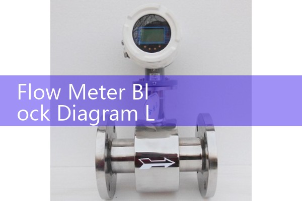
For a magnetic flow meter on a water line in Vietnam, the converter drives the coils at 6.25 Hz, 12.5 Hz, or 25 Hz depending on the application. The flow signal is often only 0.1 mV to 2 mV full scale. The input amplifier must reject 50 Hz or 60 Hz plant noise. The ADC samples the differential signal after filtering. The DSP then calculates flow velocity and totalized volume.
Silver Automation Instruments uses this layout in the SIL-MAG series converter for DN10 to DN2000 sensors. The converter supports empty pipe detection, conductivity limits above 5 µS/cm, forward and reverse flow, and 0.2 percent accuracy for water and wastewater. For slurry or chemical dosing the excitation frequency can be switched by the user.
Most engineers skip this part. Ground loops between the sensor and PLC can destroy the tiny flow signal. The converter block diagram should show galvanic isolation between sensor excitation and the 4-20 mA output. Without isolation a VFD on the same panel can cause unstable readings.
Coriolis Mass Flow Meter Signal Chain
A Coriolis flow meter block diagram is different. The sensor has a drive coil and two pickup coils. The transmitter starts the tube vibrating at its natural frequency. The two pickups measure the phase shift caused by mass flow. The digital signal converter uses a phase locked loop or frequency tracking loop, then digitizes the two sine waves with high speed ADC. The DSP computes mass flow, density, and temperature.
Temperature compensation uses a PT100 or PT1000 element on the tube. The converter stores density calibration data. For a paint manufacturer in Southeast Asia, the same Coriolis meter handles both mass flow and density without a separate densitometer. That reduces cost and pipe fittings.
Silver Instruments recommends the SIL-COR series converter w
Ultrasonic and Vortex Converter Notes
For ultrasonic flow meters, the digital signal converter controls transducer firing and measures transit time difference. The block diagram includes a high voltage pulser, receiver amplifier, time to digital converter, and flow profile correction. Silver Automation Instruments uses this architecture in the SIL-ULTRA series converter for clamp on and inline ultrasonic flow meters on chilled water, seawater desalination, and boiler feed lines.
Vortex flow meters need a different front end. The sensor is a piezoelectric element that senses vortex shedding frequency. The converter filters mechanical vibration and pipeline noise. The DSP converts the frequency to flow rate for steam, gas, or liquid. For a steam application in the Philippines, a customer used a temperature and pressure compensated vortex meter because saturated steam mass flow depends on density.
Common Output Choices and Wiring Details
In practice most plants request 4-20 mA HART as the primary output. The second output is often pulse for totalizing or RS485 Modbus for SCADA. The flow meter block diagram should identify active and passive 4-20 mA connections. Some converters support NAMUR or relay outputs for alarm and empty pipe.
A customer in Australia asked us to replace an old mechanical totalizer on a groundwater line. The new converter had pulse output and Modbus RTU. The field engineer wanted a drawing that showed terminal numbers, isolation boundaries, and earthing points. We supplied the full block diagram and wiring note before shipment. That cut commissioning time.
How to Specify a Digital Signal Converter for Your Flow Meter
Silver Automation Instruments is a flow meter manufacturer and digital signal converter supplier for industrial terminals in Asia, Oceania, Latin America, Africa, and the Middle East. Send us these data and we will select the converter board or complete flow meter: pipe size DN, flow range, fluid, conductivity for electromagnetic meters, viscosity for Coriolis, gas or steam density for vortex, temperature, pressure, power supply, and output type. We respond with a block diagram, terminal drawing, and price.
For hazardous areas we can supply Ex d or Ex ia versions depending on the zone. ATEX Zone 1 and Zone 2 are common for oil and gas sites in the Middle East and Africa. The converter must be matched to the sensor certificate and cable gland type.
Because many projects need fast delivery, Silver Automation Instruments keeps standard converter boards in stock for DN15 to DN300 electromagnetic flow meters. Larger sizes need short production time.
FAQ
Five quick answers for engineers and buyers.
What is a flow meter digital signal converter?
It is the electronic unit that drives the sensor, reads the small signal, and converts it to flow rate, total, and standard outputs like 4-20 mA HART or Modbus.
Does Silver Automation Instruments provide the block diagram and terminal drawing before purchase?
Yes. We send the internal architecture drawing and electrical connection diagram after you confirm the flow meter type and output options.
Can the converter work with a PLC or SCADA?
Yes. Standard outputs include 4-20 mA HART, pulse, RS485 Modbus RTU, and relay. We match the output to your PLC input card.
What accuracy can I expect?
Electromagnetic flow meters typically reach 0.2 percent for liquids. Coriolis mass flow meters reach 0.1 percent for mass flow and 0.0005 g/cm3 for density depending on conditions.
How do I get a price for a flow meter with digital signal converter?
Send us your pipe size DN, flow range, fluid, temperature, pressure, power supply, and output type. Call +86-25-68650347, WhatsApp +86-25-52155837, or WeChat +86 15365082610.
 Hot Product
 Related AD