

『Flow Meter Diagram Layout: Mapping Flow Elements in P&ID Industrial Blueprints』Related information(v cone flow meter|rotary gas meter|gallon meter|gear meter|metal tube rotameter|glass tube rotameter|nutating disk meter|transit time ultrasonic flow meter|wedge flow meter|pd meters|hydraulic flow meter|ultrasonic water flow meter|water flow meter|air flow meter|magnetic water flow meter|oxygen flow meter|gas flow meter|argon flow meter|air velocity meter|gasoline flow meter|fuel flow meter|ultrasonic water meter|digital water meter|nitrogen flow meter|solid flow meter|Oxygen tank flow meter|digital water flow meter|diesel fuel flow meter|steam flow meter|02 flow meter|compressed air flow meter|oil flow meter|liquid flow meter)
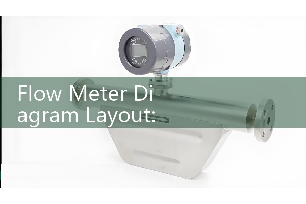
Flow Meter Diagram Layout: Mapping Flow Elements in P&ID Industrial Blueprints
Quick Answer: A flow meter diagram layout on a P&ID shows the flow element, the instrument function, the signal type, and the control loop in one view. Use ISA 5.1 symbols and tag numbers to map a flow meter correctly. For a quotation, send us your pressure in bar, temperature in °C, pipe size in DN, and flow range.
What a P&ID Flow Meter Layout Shows on a Real Drawing
A flow meter P&ID layout is not a physical installation drawing. It is a control and safety view. The drawing shows what the flow element does, how the signal travels, and where the operator sees the value.
On a typical sheet, you will see a primary flow element inside a pipe line. A bubble with a tag number sits nearby. The tag tells you the loop number, the function, and the panel location.
Many engineers start with the flow element symbol. Then they trace the signal line to a transmitter. Then they trace the output to a control system or a local indicator. Here is the thing. The P&ID is a communication tool. It is not a scale drawing.
Common Flow Element Symbols and Tag Numbers
ISA 5.1 is the base standard in many projects. You will see an orifice plate as a circle with a line across the pipe. A Coriolis meter appears as a circle with a curved tube shape or a simple circle tagged as FE. A magnetic flow meter may appear as a circle with two coils or just a tagged circle.
In practice, each project has its own legend sheet. The legend controls the final symbol. Do not guess from memory if the legend says something different.
But the P&ID legend is the final authority. A symbol often changes from plant to plant.
Tag numbers follow the first letter rule. F stands for flow. FE means flow element. FT means flow transmitter. FIT means flow indicating transmitter. FIC means flow indicating controller. FCV means flow control valve.
For a desalination plant in Saudi Arabia, a DN200 electromagnetic flow meter often appears as FIT-2301 on the brine discharge line. For a chemical dosing line in Vietnam, a DN15 Coriolis mass flow meter may appear as FE-4510 with a separate FT-4510 transmitter.
How to Read the Signal Lines and Loop Details
The signal line type carries meaning. A solid line with a slash often means a pneumatic signal. A dashed line or a solid line with a small label often means an electrical signal. Many modern drawings use a simple solid line from the flow transmitter to the DCS or PLC.
You should also read the loop sheet. The P&ID gives the tag number. The loop sheet gives the wiring terminals, the range, the calibration, and the alarm set points.
We have seen this on customer sites many times. The P&ID shows FT-3302. The loop sheet shows a 4-20 mA HART output to a PLC analog input card. The range is 0 to 80 cubic meters per hour. The fluid is raw water at 28 degrees C and 4 bar.
Mistakes We See on Customer P&ID Markups
One common mistake is using the wrong tag suffix. A flow switch should be FS not FT. A flow alarm should be FA or FAL. Mixing these creates confusion during commissioning.
Because the tag number ties the P&ID to the loop sheet, one missing digit causes a lot of confusion.
Another mistake is hiding the pipe line number. Always mark the line number close to the flow el
Do not place the flow meter symbol on a straight pipe if the actual installation needs upstream and downstream straight runs. For vortex and ultrasonic meters, mark the straight run requirement on the drawing. For example, Silver Instruments SIL-VOR vortex flow meter needs 15D upstream and 5D downstream for clean liquids on a DN80 line.
Recommended Flow Meter Models by Application
For liquid chemicals and high accuracy mass flow, use a Coriolis meter. Silver Instruments SIL-COR works on flows from 0.1 kg/h to 500 t/h. It outputs 4-20 mA HART and can fit DN15 to DN200 lines. Use this for a paint manufacturer in Southeast Asia that batches resins and solvents.
For water, wastewater, and desalination brine, use an electromagnetic flow meter. Silver Instruments SIL-MAG covers DN10 to DN3000. It handles conductivity above 5 µS/cm. A customer in Chile uses a DN150 SIL-MAG on raw water with a 4-20 mA HART signal to a PLC. For oil and gas skids in Brazil, specify the same SIL-MAG with ATEX Zone 1 certification and a remote converter.
For steam and compressed air, a vortex flow meter is common. Silver Instruments SIL-VOR handles saturated steam up to 240 degrees C and pressure up to 25 bar. Use a DN50 meter on a 6 bar compressed air header in a food plant in Vietnam.
For diesel, heavy oil, and lubricating oil, an oval gear flow meter works well. Silver Instruments SIL-OG covers DN4 to DN80 and viscosity up to 2000 cP. A distributor in Nigeria uses a DN25 oval gear meter on a diesel filling skid.
For biogas and flare gas, thermal mass flow meters give direct mass flow. Silver Instruments SIL-TH works on low flow and low pressure gas lines. It has no moving parts and can include a PT100 temperature output.
Send Us Your P&ID Details for a Quote
Do not send a full drawing unless you must. Send the flow element tag number, pipe size, fluid, flow range, pressure, temperature, and signal type. Our engineers will match the meter to your P&ID and suggest a model.
Contact Silver Automation Instruments. Tel: +86-25-68650347. Whatsapp: +86-25-52155837. WeChat: +86 15365082610. Website: flow-meter.com.au
Tell us the application and the country. We quote for Southeast Asia, Oceania, Latin America, Africa, and the Middle East.
FAQ: Flow Meter Diagram Layout in P&ID
What does FE mean on a P&ID? FE means flow element. It is the primary sensor in the pipe. The transmitter is often shown as FT.
What is the difference between FT and FIT? FT means flow transmitter. FIT means flow indicating transmitter. FIT adds a local or panel mounted display.
Can I use the same symbol for all flow meter types? No. Each project legend may show different symbols for electromagnetic, Coriolis, vortex, and oval gear flow meters. Always follow the legend sheet.
Why do some P&ID circles have a line through the middle? A line through the bubble often means panel mounted or DCS accessible. A bubble without a line often means field mounted. Check the legend because some sites use the opposite rule.
How do I request a quote from a P&ID? Extract the tag number, pipe size, fluid, flow range, pressure, temperature, and output signal. Send these details to Silver Automation Instruments on Whatsapp or WeChat.
 Hot Blog
 Related AD